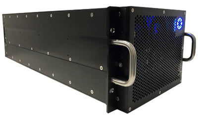
Edge computing is loosely defined as enterprise or industrial computing outside of a datacenter. The environments which encompass edge computing pose a unique set of challenges, requiring hardware to be designed to have a broad set of thermal and structural characteristics. For example, an edge computing device designed for an outdoor telecommunications application may be exposed to an extensive range of operating ambient temperatures, but it will experience little to no structural vibration or shock forces. Conversely, compute systems operating in vehicles, ranging from commercial cars & trucks to military drones, will be exposed to vibration levels which pose significant threat to the electronics within. A common approach to addressing the thermal and vibration challenges of these complex environments is to compromise in terms of performance and use lower power, lower performing components. Lower power components generate less heat and are designed in form factors, which can natively withstand higher vibration or shock levels than their higher-performing enterprise counterparts. Many of the latest edge AI (Artificial Intelligence) applications, however, require the highest performing compute possible to avoid introducing bottlenecks in software capabilities and feature development. Future edge-optimized components may provide a long-term roadmap for these applications, but the ideal solution for current high-performance edge-applications requires adapting existing enterprise electronics with maximum compute performance to these edge environments. Companies developing these types of products provide a valuable path for quicker time-to-market for edge AI platforms.
When addressing the issue of integrating enterprise electronics into edge systems, one thing is clear: enterprise components are not natively designed for high vibration environments. A key element of a high-performance edge AI compute platform is the GPU(s). The latest enterprise GPUs (i.e., NVIDIA H100) are relatively bulky, heavy, high heat generating devices which typically are only held in place by a friction lock in the add-in card PCIe slot combined with two fasteners clamping a mounting bracket to a sheet metal enclosure. This form factor can have strong benefits in terms of the power/performance per square inch and its thermal conductivity in high airflow, but it causes a structural risk when integrated in vibration or shock environments.
 The failure modes which can occur when these types of electronics are exposed to vibration can vary, but the failures can typically be divided into two categories: intermittent failures or long-term failures. Intermittent failures can occur when add-in cards in edge systems are not properly secured along the entire length vertically within the motherboard or expansion slot. For example, as the edge device vibrates in an environment like a moving vehicle, there can be a resonance stack-up from vehicle to system to motherboard/backplane to the add-in card. The resulting superposition can cause momentary disconnection of the add-in card from the PCIe slot, which will subsequently cause data errors or a loss of connection between the add-in card and the system altogether. While these types of failures can typically be resolved by a system reboot, they cause disruptive operating failures in the compute platform which can be a safety, reliability, or performance concern. Long-term failures occur when vibration affects the system for a sustained period of time at a high enough level to wear the components to a point of ongoing intermittency or permanent failure. These are most seen in physical wear markings on components due to friction – where edge connections are worn beyond an operational level. These long-term failures are preventable to a degree – but the target lifecycle of the system must be considered as a design element. While some edge systems are expected to be replaced every 1-2 years, other systems must survive up to 5 years and beyond, while being subjected to constant vibration.
The actual degree to which the effects of intermittent and long-term vibration failures on enterprise electronics can be mitigated in edge environments depends on the specific challenges of the environment and the size, weight, and power (SWaP) constraints therein. The first step in mitigating long-term detrimental effects to an edge device is to properly characterize the boundary conditions to understand their corresponding impact on the components within. For most vehicular applications, there is an industry standard which can be used to define the vibration profile of the vehicle (i.e., MIL-STD-810 for military vehicles). Once the input profile is defined – the next consideration is the mounting scheme of the system within the vehicle. To mitigate vibration response at a mounting fixture level, the system should be mounted in a balanced manner to avoid cantilever mechanics, and components such as shock isolators or dampening coils can be incorporated to mitigate specific resonance frequencies which may be native to the vehicle. The primary fixture points should also be spaced away from the sensitive electronics – with fasteners dividing the space between mounting point and component to minimize the potential displacement during resonance modes. A sufficiently designed mounting fixture should have its own primary natural modes at a significantly higher frequency than the modes of concern in the region of the sensitive components to avoid a multiplicative impact. To increase the frequencies of the natural modes – the fixture should be optimized for its stiffness to mass ratio – either through material selection, mechanical features, or addition of fasteners in select locations.

For system designs to mitigate vibration effect on enterprise electronics, the region around the electronics themselves should be optimized to avoid resonance around the natural resonance imposed by the vehicle. For example, some propeller-driven aircraft have propeller harmonics at 68 Hz, which can cause resonance build-up in systems throughout the aircraft. In designing a system with enterprise electronics, analysis should be done on the system to verify there is no system level resonance at or near the 68 Hz mark, which could cause a multiplicative effect. This can be mitigated by adding or moving bracing structures near key components to ensure there are not long, unconstrained sections. A general rule of thumb is to aim for no natural resonance under 100 Hz, with significant mass participation, particularly around sensitive components. For add-in cards, while the fixture and system design can mitigate a sizable portion of the vibration response, the cards themselves should be further constrained. For heavy add-in cards such as GPUs, the cards should ideally be constrained using their normal PCIe bracket, a locking PCIe connector, a rear retention bracket, and a vertical axis top compression device. While the PCIe bracket and locking connector are relatively standard – the rear and top retention mechanisms often require custom design to fit the needs of the system and target environment. These customizations are an opportunity to perform analysis and to mitigate specific target resonance, which may be an issue in the target vehicle. The top retention mechanism can vary from a compression foam dampener to a fixed-position bracket acting as a horizontal barrier, preventing cards from coming out of the slot. In any design case, analysis and testing should be performed to verify mitigation of both the intermittent effects and long-term impact for the required life of the unit.
Overall, mitigation of vibration in edge deployment of enterprise electronics is often overlooked because the results of a failure may not be seen for a long duration of exposure, or a system integrator might take the easy route by compromising on system performance by selecting a low-performance embedded device option. However, through careful analysis, design principles, and testing, a system which has been properly designed can make effective use of the power and performance of enterprise electronics in unfriendly environments. Input vibration definition, mounting fixturing, system design, and add-in card bracing are key elements which can be customized to address the rigors of a harsh environment and the compute-performance requirements of the edge application. Through these design principles, the definition of “edge” devices can be broadened beyond simple low-performance embedded platforms to take advantage of the latest in enterprise technologies.
Click the buttons below to share this blog post!
View our infographic showing the best advanced thermal management methods for edge AI computing.

As we bring another successful year to a close, we at One Stop Systems (OSS) are incredibly proud of the progress we’ve made — progress that directly translates into greater capability and success for you, our valued customer. We’ve expanded our product portfolio and deepened our technical expertise, driving measurable impact across both Commercial and Defense markets.

By: Jaan Mannik – Director of Commercial Sales
The term AI, or Artificial Intelligence, is everywhere nowadays and has quietly woven itself into the fabric of our daily lives. It powers the recommendations we see on streaming platforms, the navigation apps that guide us through traffic, and even the virtual assistants that answer our questions in seconds. From optimizing energy use in smart homes to predicting market shifts in finance, AI has become the invisible engine driving convenience, efficiency, and insight across industries.
In manufacturing, AI-driven robots collaborate with humans to streamline production. In agriculture, machine learning models monitor crops, forecast yields, and conserve resources. Retailers use predictive analytics to anticipate consumer needs before customers even express them. The reach of AI is no longer confined to futuristic labs, it’s in our phones, vehicles, and cities, constantly learning and adapting to serve us better.

OSS PCIe-based products deliver critical advantages for modern military sensor systems by enabling real-time data acquisition, processing, and transmission in rugged, mission-critical environments. These benefits stem from their ability to support high-bandwidth, low-latency interconnects, modular scalability, and environmental resilience, all of which are essential for today’s advanced military platforms.